Let's talk about the guitar's best friends, overdrive and distortion. Modern music hasn't been the same since the 60's and early 70's when some of the most iconic dirt boxes were created! To this day a lot of pedals have been part of many debates... is it an overdrive or a distortion. Recently, overdrive has been associated with circuits that employ the "soft clipping" architecture and distortion would be circuits that employ the "hard clipping" architecture. So what's the difference, really?
Soft Clipping vs. Hard Clipping
An operational amplifier (op amp) is an integrated circuit that can amplify weak electric signals and are the key to most overdrive and distortion pedals. They boost the guitar signal to a level loud enough for the sine wave to be manipulated. While not all overdrive and distortion pedals use op amps to boost the guitar signal, they will be the key of our topic today.
Soft Clipping is when the guitar signal / sine wave gets clipped in the feedback loop of an op amp. Hard Clipping is when the guitar signal gets clipped after the feedback loop. So what is a feedback loop? This is the portion that is used by the op amp to amplify the guitar signal, it's a loop that connects the input to the output of the op amp. Reverence the images below for the difference between the two methods.

Soft and Hard Clipping got their names from the way the original sine wave looks after it has been clipped. See the three images below, the first one is the original sine wave that has been unaffected. The second is considered Soft Clipping and the third is Hard Clipping. As you can see the Soft Clipping has softer edges and the Hard Clipping has very hard/ridged edges.


You'll also notice that the sine wave for the Soft Clipping circuit looks much closer to the original sine wave than Hard Clipping does. The result is a more natural sounding overdrive as less of the original sine wave has been modified or clipped off. The opposite is true of Hard Clipping, the end result doesn't even resemble a sine wave anymore, in fact it looks almost exactly like a square wave.
Clipping Diodes and Their Effect
Now that we've gone over the basics of the sine waves associated with an overdrive and a distortion circuit. I want to go a bit deeper into clipping diodes and their affect on the sine wave. Remember above when I said how the op amp boosted the signal so we can manipulate it? This is where the diode comes in, when placed in the signal path it has a predetermined voltage level that won't let current pass through, which in turn means clipping! Once the guitar signal is boosted high enough, then the clipping diodes start to take effect by altering the original sine wave.
Looking at the picture above (Soft vs. Hard Clipping) the diodes are reference by the symbol that looks like a triangle with a line above it. You'll notice in both examples the circuit designer used two diodes and each one faces the opposite direction. This is called symmetrical clipping, meaning the top of the sine wave gets clipped equally as much as the bottom of the sine wave. If the designer wanted asymmetrical clipping, he could use two diodes in series facing one direction and one diode facing the other direction. This will clip the top of the sine wave less than the bottom of the sine wave, resulting in a more complex overdrive/distortion sound. Let's look at a few examples of how diodes affect the sine wave using the output of the JET Lamb Overdrive as an example. The first picture is our Blue Mode (quad silicone symmetrical diodes), the second picture is our White Mode (three silicone asymmetrical diodes) and the third picture is our Yellow Mode (only one diode clipping the bottom of the sine wave).
Quad Silicone Diodes

Asymmetrical Silicone Diodes

One Diode Clipping the Bottom Only

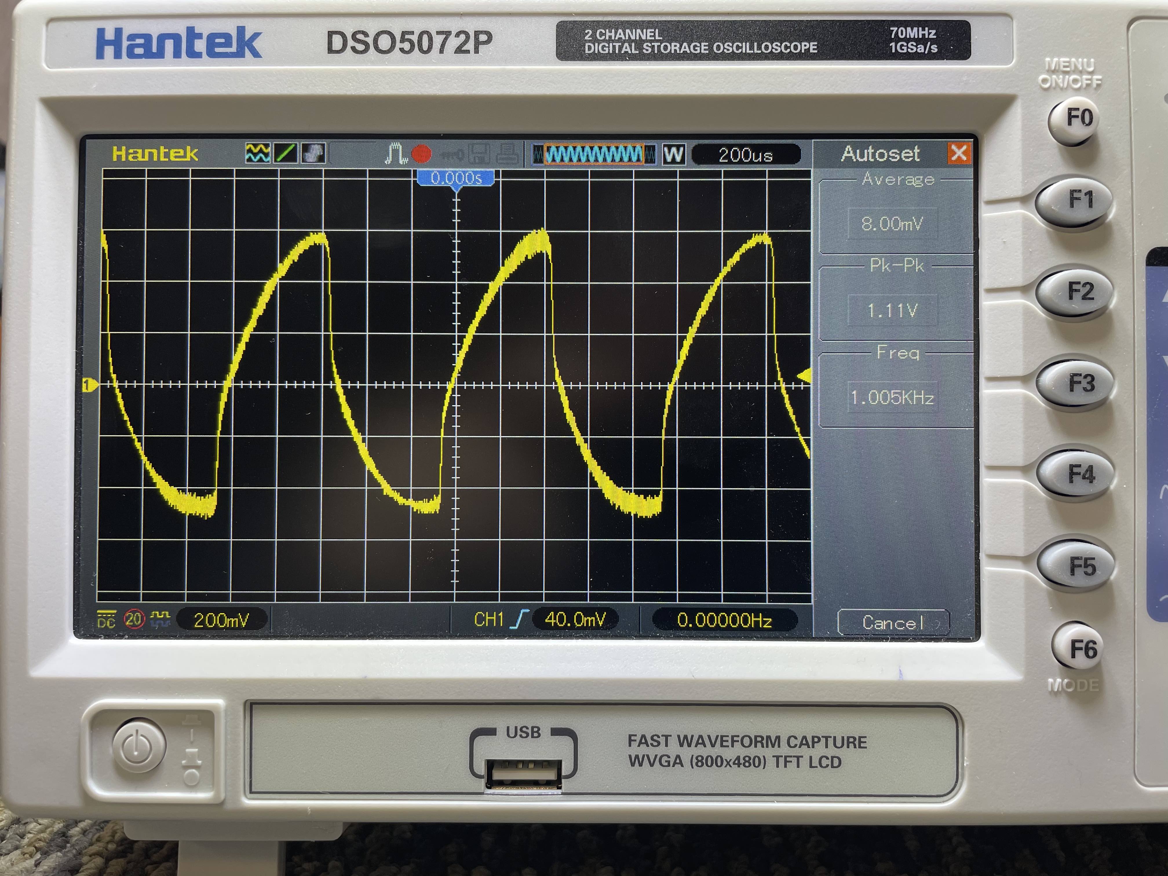
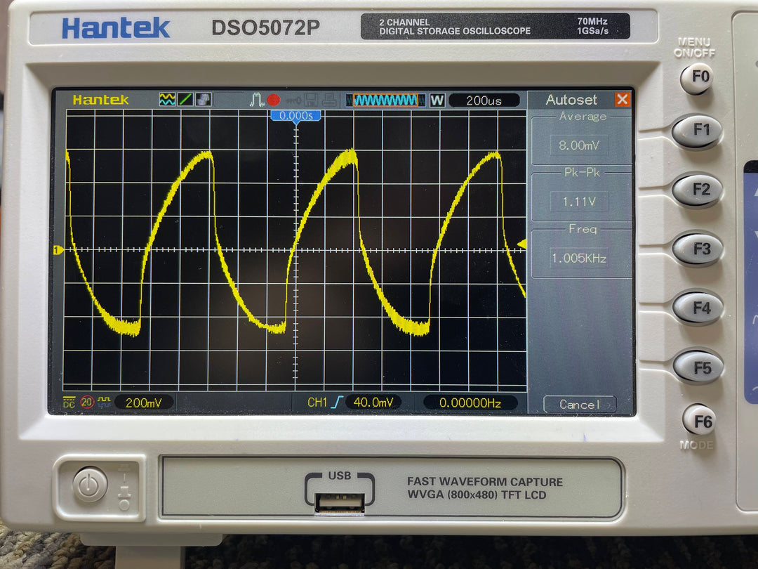
Notice in the last picture the sine wave is very unique, this is because we only placed one diode in the feedback loop. The result is the top of the sine wave is almost completely unaffected, it has some alteration which is due to the tone knob but more on this later. The bottom of the sine wave almost looks like that of a distortion circuit, this is because we set the threshold for the single diode really low. See the crosshairs that looks like a cross with 4 dash marks per every square, this is considered the zero reference line and the sine wave crosses both above and below this line. Notice how the top goes way above the line and the bottom is much closer to the line? This is how compressed the sine wave is, the top is almost uncompressed but the bottom is squashed down pretty close to the zero line. This is our favorite Mode in the Lamb as it still feels open like a transparent overdrive but also compressed and heavy like a distortion.
Now let's look at what the clipping diodes look like with the JET Lion distortion pedal. The first picture is our Blue Mode (Symmetrical dual silicone diodes), the second picture is our White Mode (Asymmetrical three silicone diodes), and the last is our Yellow Mode (Symmetrical dual red LEDs).
Symmetrical Dual Silicone Diodes

Asymmetrical Silicone Diodes

Symmetrical Dual Red LEDs

Looking at these three sine waves you can see that the Blue Mode will be the heaviest sounding clipping options as it closely resembles a square wave and is also the furthest away from the original rounded sine wave. The White and Yellow Modes look very similar, however if you look closely at the bottom of the sine wave this is where they start to look different. The White Mode starts to resemble a Soft Clipping wave form but also has a very hard cut off on the other side of the sine wave. The sound of this mode will still sound like distortion, however the softer edge means it will compress less and will be better suited for Rhythm chords as you’ll get better note definition than the super compressed Blue Mode. The Yellow Mode is similar to our Lamb where you get a blend of distortion and overdrive. Unlike the Lamb, where the overdrive is more present than the distortion, the opposite is true for the Lion. In this mode the distortion is most present (look at the bottom of the sine wave) however the softer edges of the top of the sine wave give you a very open sounding distortion.
Now let's see how the tone knob can also shape the overall sound of an overdrive or distortion pedal. The two pictures below is from the Lion in the Blue Mode however instead of the High Cut knob at noon (less treble) we’ve started to turn down the knob (more treble). Basically the less treble that is present in the signal path, the more it will smooth out the edge of the sine wave. More treble does the opposite - it will sharpen the edge of the sine wave.
High Cut at Noon (Less Treble)

High Cut at 25% (More Treble)
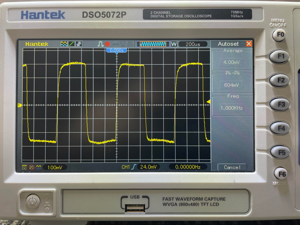
High Cut Turned Off (The Most Treble)

I hope this gives you a better understanding of the differences between overdrive and distortion, including the effects that various clipping diodes will have on the overall sound of the drive. As you can see the designer has many different options they can choose to really dial in the sounds of their drive box. In fact we only went over two different types of diodes (silicone and Red LEDs) and there are many more out there the designer can pick to fine tune the sound of their drive. But that’s a topic for another day… :)
Drop us a line in the comments section and let us know what’s your favorite style, overdrive or distortion? Also let us know which is your favorite drive pedal?
Until next time…
-Junior “JET” Thomason



This was fantastic, much appreciated! I’m a novice with electronics, and I could understand this article.
Leave a comment